Sure! Here’s the rewritten content in English:
---
AC motors operate based on the same fundamental principles, but by tweaking their design slightly, they can be tailored to meet specific application needs. In my previous post, I focused on AC induction motors for unidirectional applications. Today, I’ll explore what makes AC reversible motors and AC electromagnetic brake motors ideal for start/stop, reversing, or vertical applications. I’ll also walk you through how to operate them.
### Reversible Motors
Let’s first clarify why reversible motors are called “reversible.†All permanent split capacitor type AC motors are reversible. However, induction motors cannot reverse direction instantly—they need to stop completely first. Reversible motors, on the other hand, can change direction much more quickly. For instance, while induction motors can reverse by switching the lead wires, they have about a 30-revolution overrun compared to a mere 5-revolution overrun offered by reversible motors, making them less suitable for applications requiring instant reversal.
The overrun refers to the number of revolutions the motor shaft completes after power is removed. According to Newton's First Law of Motion, objects in motion tend to stay in motion unless acted upon by an external force, such as friction. Reversible motors use a friction brake that significantly reduces this overrun by applying pressure against the armature when instructed to stop. The holding torque provided by the friction brake is approximately 10% of the motor's output torque, which can be enhanced by the gear ratio. However, this isn’t designed for vertical holding—it’s meant to minimize overrun.
Another key difference is the use of balanced windings. Balanced windings ensure that the primary and secondary windings have identical resistance and inductance, allowing the motor to produce equal torque regardless of which phase is energized or which direction it’s rotating. Combined with the friction brake, these features enable seamless direction changes.
Due to the constant friction between the brake and the armature, we use capacitors rated higher than those used in induction motors to provide extra starting torque for reversing. While the increased operating temperature means a reduced duty cycle (50%, or 30 minutes max continuous operation), as long as the motor case temperature stays below 100°C, the motor will last.
### Theory of Operation
When power is supplied to the copper windings in the stator, a rotating magnetic field forms around the rotor at the frequency of the AC supply. By Fleming's left-hand rule, this magnetic field induces a current in the aluminum bars of the steel rotor, creating opposing magnetic fields (as per Lenz's Law). These fields interact with the stator’s magnetic field, causing the rotor to begin spinning.
If you’re interested in learning more about the operational theory of AC motors, feel free to check out our white paper on AC Motor Fundamentals.
### Wiring
Here’s the wiring diagram for single-phase reversible motors (which is similar to single-phase induction motors). Three-phase motors are typically paired with inverters or VFDs for continuous speed control, so three-phase reversible motors aren’t as common.
The rotation direction of the motor depends on which terminal the live wire is connected to, and the red wire indicates the output shaft side of the motor.
For standard 3-wire motors, the lead wire colors are white, red, and black. Black connects to neutral (N), while both white and black connect to the capacitor terminals. Connecting the live wire to either the black or red via the capacitor terminals determines the motor's rotation direction. For terminal box-type motors, the same principle applies, but the terminals are labeled Z2, U2, and U1.
### The Capacitor
In single-phase motors, the capacitor plays a crucial role in startup. Without it, you’d have to manually rotate the shaft to get the motor started—a bit like pushing a vintage airplane propeller. Be sure to wire the capacitor correctly, as improper wiring was a common troubleshooting issue back when I worked as a tech support engineer.
Here’s an example of wiring a 4-terminal capacitor with a single-phase motor. Don’t be confused by the number of terminals—the internal wiring diagram shows that the two closest terminals are internally connected, effectively making it the same as a traditional two-terminal capacitor.
Remember to ground the motor using its dedicated protective earth grounding terminal (PE) to avoid electrical hazards.
Check out this video to see how the standard wiring looks:
### Electromagnetic Brake Motors
An electromagnetic brake motor is essentially a reversible motor equipped with a power-off-activated electromagnetic brake. Like reversible motors, the duty cycle is limited to 50% (or 30 minutes max continuous operation). However, electromagnetic brake motors offer shorter overrun and greater holding torque.
Designed for vertical applications like load elevators, the electromagnetic brake produces torque close to the motor's rated output, keeping loads secure even if power fails mid-operation.
The electromagnetic brake locks the motor shaft to hold the load in place. It reduces overrun from 30 revolutions to just 2-3 revolutions. For start/stop applications, the maximum operating cycle is 50 cycles per minute or fewer. For higher cycles, consider a brake pack, clutch and brake motor, or high-efficiency stepper motors.
The electromagnetic brake operates on the same voltage as the motor. When the magnet coil is energized, it becomes an electromagnet, attracting the armature against the spring force, releasing the brake, and allowing free rotation. When de-energized, the spring presses the armature against the brake hub, locking the motor shaft.
Compared to induction and reversible motors, wiring electromagnetic brake motors is more complex due to the additional components. A capacitor is also needed for single-phase models. Three-phase versions are available for variable speed applications because the base motor is a continuous-duty induction motor rather than a duty-limited reversible motor.
Refer to the wiring diagram below for guidance:
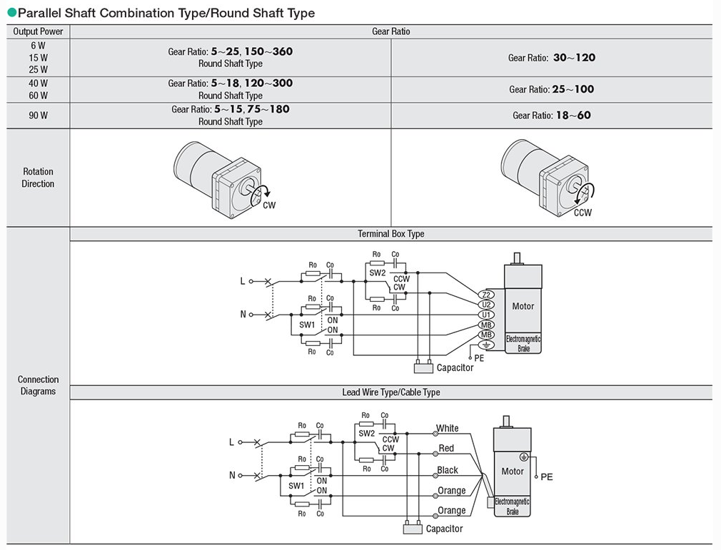 This setup ensures the brake engages when the motor stops and disengages when running.
Watch this video to see proper wiring, including circuit breakers, switches, and CR circuits for surge suppression:
### Overrun and Duty Cycle Comparison
Here’s a summary of the main differences between induction motors, reversible motors, and electromagnetic brake motors:
| Type of Motor | Overrun | Duty Cycle |
|------------------------------|-----------------|------------------|
| Induction Motor | 30~40 revolutions | Continuous |
| Reversible Motors | 5~6 revolutions | 50% |
| Electromagnetic Brake Motors | 2~3 revolutions | 50% |
The overrun value is for the motor shaft. You can reduce overrun by adding a gearhead with a high ratio, increasing friction, or decreasing load inertia.
The duty cycles mentioned are recommended values. As a general rule, keeping the motor case temperature below 100°C ensures optimal performance.
That wraps up AC reversible motors and AC electromagnetic brake motors. Stay tuned for my next post on the torque-speed characteristics of AC motors, and remember to subscribe!
To learn more about the KII & KIIS Series, here’s a quick overview video:
---
I hope this version is more engaging and easier to read! Let me know if you'd like further adjustments.
This setup ensures the brake engages when the motor stops and disengages when running.
Watch this video to see proper wiring, including circuit breakers, switches, and CR circuits for surge suppression:
### Overrun and Duty Cycle Comparison
Here’s a summary of the main differences between induction motors, reversible motors, and electromagnetic brake motors:
| Type of Motor | Overrun | Duty Cycle |
|------------------------------|-----------------|------------------|
| Induction Motor | 30~40 revolutions | Continuous |
| Reversible Motors | 5~6 revolutions | 50% |
| Electromagnetic Brake Motors | 2~3 revolutions | 50% |
The overrun value is for the motor shaft. You can reduce overrun by adding a gearhead with a high ratio, increasing friction, or decreasing load inertia.
The duty cycles mentioned are recommended values. As a general rule, keeping the motor case temperature below 100°C ensures optimal performance.
That wraps up AC reversible motors and AC electromagnetic brake motors. Stay tuned for my next post on the torque-speed characteristics of AC motors, and remember to subscribe!
To learn more about the KII & KIIS Series, here’s a quick overview video:
---
I hope this version is more engaging and easier to read! Let me know if you'd like further adjustments.Stainless Steel Coils ,625 Nickel Alloy Strip ,2207 Coil Strip,Nickel Alloy Foil
Ningbo Boss Metal Material Co., Ltd. , https://www.boss-metal.com