Author: Lvguo Juan Summary:
I. Overview
1.1 Project and Main Auxiliaries Overview
Yang Electric Co., Ltd. is located on the northwest side of Wantou Town in the northeastern suburb of Yangzhou City. The Yangzhou Power Generation Co., Ltd. project is the construction of two new 300MW coal-fired generating units. The boiler is a 300MW domestically-imported subcritical parameter, natural circulation, single steam package, single furnace, tangentially-fired tangent, an intermediate reheat, balanced ventilation, open-air layout, all-steel framework, coal-fired, solid state slag discharge furnace. . 
The steam turbine is a subcritical, once reheat, double-cylinder double-exhaust, single-back pressure extraction condensing steam turbine generator set in Harbin Steam Turbine Works. 
The generator uses a 300MW water-hydrogen-hydrogen turbine generator produced by Harbin Electric Machinery Factory with the introduction of Westinghouse Technology. Model: QFSN-315-2. 
Each boiler is equipped with 5 coal mills, 4 transports and 1 standby, and 5 pressure-resistant electronic weighing coal feeders are also equipped. In addition, each furnace is equipped with 2 single-suction, double-support centrifugal primary fans, 2 adjustable-flow axial-flow fans, and 2 static-adjustable axial-flow suction fans. The air preheater is a three-position, space-occupying double seal air preheater.
Each turbine is equipped with a simplified high- and low-pressure series bypass system with a capacity of 30% B-MCR. Set up 2 sets of 50% B-MCR speed-regulated steam feed water pumps and 1 set of 50% B-MCR backup speed-regulated electric feed pumps. Each unit is equipped with 2 sets of 100% capacity electric condensate pumps. The medium-pressure condensate polishing device (one set per machine) consists of two filters and two mixed beds, and a combination of two sets of regenerators is used.
1.2 Distributed Control System (DCS) Overview
The DCS of the project's decentralized control system adopts the XDPS-400 system of China-made Xinhua Control Engineering Co., Ltd. 
The configuration and functional design of the decentralized control system should be completed in accordance with the requirements of the entire plant automation level. The engineering unit unit adopts a decentralized control system, the auxiliary production workshop adopts a programmable controller technology, and the unit unit and the auxiliary workshop have a high level of automation. The factory also set up a plant-level monitoring information system (SIS) to coordinate the operation and production management of each unit and plant in real time. 
The DCS control range includes boilers and their auxiliary systems, turbine generator sets and their auxiliary systems, oxygen removal water supply systems, high and low voltage plant power systems, generator transformers and common parts of the two units. At the same time with the turbine TDM, power plant real-time information management system (SIS), the whole plant clock synchronization system, automatic excitation adjustment system, pseudo synchronous system (ASS), relay protection system and auxiliary system (PLC control system, such as supply water, gray Slag, coal transportation, etc. for communication, to achieve a unified monitoring and management of the entire plant. 
The DCS main functions include the following: DAS, MCS, SCS, FSSS, ECS and common parts of the two units . 
Second, the decentralized control system (DCS) configuration
2.1DCS network structure
The XDPS-400 system of this project is a ring-shaped optical Ethernet network. The network configuration is shown in the figure below. 
The network structure of the unit unit DCS is ring-shaped, connecting each distributed processing unit, input/output processing system, human-machine interface and system peripherals; the common DCS system adopts a star structure. The unit DCS and public DCS systems are isolated by XDPS bridges.
Redundant data communication buses (including redundant communication bus interface modules) are hot standby. The system network backbone is composed of three 10Mbps data communication networks, RTFNET (redundant), and INFNET network is a high-speed data management information network. The RTFNET network mainly completes the transfer of real-time data. The INFNET network implements non-real-time data transfer, such as historical data calls. All DPUs (Distributed Processing Units) are connected to the RTFNET network. All human-machine interfaces are connected to the RTFNET and INFNET communication networks at the same time. There is no intermediate database communication device. The main technical data of the network of the circulating water pumping house remote station adopting the redundant fiber optic FCS bus to complete each layer of the network is shown in Table 2 below.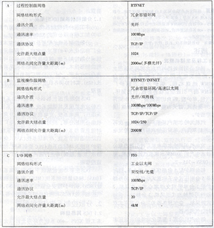
2.2DCS hardware configuration
2.2.1 The number of I/O signals is as follows:
I, boiler section
 II, boiler section remote  III, steam turbine section
   IV, boiler section remote
   V, electrical power generation unit and factory power supply section
   VI, summary of a single boiler 3106 points, follow the pump room 302 points,
Single steam turbine 2651 points, furnace common 129 single electrical hair change group 729 points, electrical public 177 points 2.2.2 DCS hardware equipment
The hardware equipment of each unit unit distributed control system of this project mainly includes: 50 cabinets, 5 sets of operator stations, 2 sets of engineering stations, 1 set of historical data stations (HSU), 1 set of performance calculation stations, 1 set of valued stations. . 
The specific cabinet distribution is as follows:
Public System XDPS-400 Hardware Device DCS man-machine interface station (MMI) interface equipment includes operator station, engineer station, historical data station, performance calculation station, value long station number and performance are shown in the table below
 2.3 system hardware characteristics
2.3.1 Communication Network
The network part of Yangdian Engineering's XDPS system uses ring-shaped optical Ethernet. Its core component, the network switch, uses a 10/100M adaptive RS2-FX/FX Ethernet fiber switch from HIRSCHMANN of Germany. 
In the traditional Ethernet structure definition, the Ethernet topology is defined as a bus or star structure and there is no ring to say. The failure of any transmission medium or transmission device in the bus or star network will cause the original integrated network to be divided into two separate segments, thus causing the communication between the network nodes to be interrupted. HIRSCHMANN's ring-shaped Ethernet network solves the problem of network connectivity caused by the failure of a single transmission medium or transmission equipment in the network structure, thereby greatly improving the reliability of the network. 
The core component of the ring network, the RS2-FX/FX Fiber Switch, provides the functionality of the Redundant Manager. Switches configured as RM Managers exist as logical breakpoints throughout the ring physical network. In other words, although the ring Ethernet is physically a ring structure, it is logically a bus structure. When a certain optical fiber or a certain switch fails, the ring network physically degenerates into a bus-shaped network, but the characteristics of the logical bus do not change, and each node in the network also works as a normal bus or a star network. The fault tolerance of the entire network has been greatly enhanced. 
Using optical fiber as the optical transmission medium solves the problem of poor anti-electromagnetic interference performance of the communication cable, and at the same time, creates conditions for establishing communication between remote controllers. The utility circulating water pump DCS control equipment is far from the edge of the plant, and the 500 meters of optical fiber cable enables the unit control room to monitor the pump room equipment. 
In the above network configuration diagram 1, the network structure of the unit set DCS is ring-shaped, and the public DCS system uses the star structure. The DCS between the unit unit DCS and the public DCS system is isolated through the XDPS bridge, and the relative independence between the unit unit and the DCS of the public system is maintained. The bridge completes the real-time data transmission process between the DCS of the unit unit and the public DCS system: 1. The bidirectional real-time process volume is transferred; 2. The operation instructions issued by the unit unit operator station are unidirectionally transmitted to the public DCS system. The database of the unit unit and the public system is independent, and the changes in the hardware and software structure of the unit DCS system have no effect on the public system. 
In the distribution of network nodes, the principle of relatively independent peer-to-peer communication between nodes is followed. The Ethernet switch has the function of offloading the data of each port according to the MAC address of the network data frame, and unlike the HUB, each port is filled with related and unrelated data packets. In the XDPS system, there is point-to-point real-time data tracking and copying between redundant DPUs. By connecting the relevant redundant DPUs on the same switch, the point-to-point data transmission between the redundant DPUs is directly forwarded on the local switch, thereby reducing the network load of the backbone ring network. 
2.3.2 Controllers
Distributed processing unit DPU is the process control station of XDPS-400 and is the core of DCS. The DPU is a small industrial PC that uses the Intel Pentium 266 CPU, 32MB RAM, ISA bus board, and read-write permanent memory Disk0nChip24MB. The distributed processing unit DPU stores system information and process control strategies and data, implements various control strategies through redundant and bidirectional information exchange, and completes functions such as data acquisition, simulation adjustment, sequence control, advanced control, and expert systems. The processor module uses DOC chip technology, eliminating the need for back-up batteries. And also has the following characteristics:
2.3.2.1 A processor module failure does not affect the operation of other processor modules. In addition, the processor module can continue to operate when the data communication bus fails. 
2.3.2.2 The removal, modification or restoration of a processor module will not affect the operation of other processor modules. 
2.3.2.3 Redundant configuration of all control processors. Once a working processor module fails, the system can automatically and quickly switch to its redundant processor module in a non-intrusive manner and alarms at the operator station. . 
2.3.2.4 Redundantly configured processor modules and systems have parallel independent interfaces, ie they can all accept the online configuration and configuration modifications of them. The processor module in the standby state can constantly update its own information. 
2.3.2.5 Various types of data information of the system's control and protection functions will not be lost or delayed due to redundant switching. 
2.3.2.6 Power failure is a recoverable failure of the system. Once the power is restored, the processor module can automatically resume normal operation without any intervention from the operating personnel. 
The unit unit has a total of 19 pairs of DPUs and two pairs of communication DPUs that are responsible for communicating with the peripheral PLCs. Communication uses widely used, ready-made communication protocols such as TCP/IP, MODBUS, MODBUSPLUS or PROFIBUS. The public system sets 4 pairs of DPUs. Circulating pump room 4 For the DPU, an engineering station is set up for the utility system. There is no separate operator station. 
Third, the decentralized control system function
3.1 Data Acquisition System (DAS): DAS has at least display, tabulation records, historical data storage and detection, performance calculation and other functions.
3.2 Analog Control System (MCS)
3.2.1 boiler-turbine coordination control
3.2.2 unit load command
3.2.3 Turbine Control
3.2.4 Boiler Control
3.2.4.1 Coal Mill Control
3.2.4.2 Secondary air volume control
3.2.4.3 Bellows Baffle Control
3.2.4.4 Primary Air Pressure Control
3.2.4.5 Furnace Pressure Control
3.2.4.6 Main Steam Temperature Control
3.2.4.7 Reheat Steam Temperature Control
3.2.4.8 Water Supply Control
3.2.4.9 Feedwater Pump Recirculation Control
3.2.4.10 Air Preheater Average Cold Temperature Control
3.2.4.11 Fuel Control
3.2.5 Deaerator water level and pressure control
3.2.6 Condensate hot well water level control
3.2.7 Turbine Lubricating Oil and EH Liquid Cooling Control
3.2.8 High and Low Pressure Heater Water Level Control
3.2.10 Other Single Impulse Closed Loop Control Systems
3.3 Boiler furnace safety monitoring system (FSSS)
3.3.1 BCS function: It should include the boiler ignition preparation, ignition gun ignition, oil gun ignition, coal combustion function. 
3.3.2 FSS function: It should be completed by furnace purging, oil fuel system leakage test, fuel tripping three systems. 
3.4 Sequence Control System (SCS <B/T, G/T)
3.4.1 Boiler Function Subgroup Control Items
(1) Air preheater subgroup items
(2) Blower subgroup item
(3) Induced fan subgroup item
(4) Primary fan sub-group item
(5) Boiler Drainage, Steam Ventilation, and Regular Sub-process Control Subgroups
(6) Soot blower control system
(7) Electric-powered pump sub-group item
(8) Steam driven water pump sub-groups
3.4.2 Steam Turbine Function Sub-Group Control Projects
(1) Steam engine oil sub-group items
(2) Condensate water subgroup item
(3) Condenser subgroup items
(4) Condenser vacuum system subgroup items
(5) Turbine shaft seal system subgroup items
(6) Low-voltage heater subgroup items
(7) High Voltage Heater Subgroup Item
(8) Steam turbine steam trap subgroup items
3.4.3 high and low pressure bypass control function
3.4.4 circulation pump function subgroup
3.4.5 Generator and Generator Power System Control (SCS<G/A) Specific Functions 3.4.5.1 Generator Transformer Function Group: Including the synchronous system, generator transformer line group system, and generator excitation system control functions.
3.4.5.2 Plant power system function group: Including 6kV factory work power system, 220kV standby power system, 380V factory work power system, security power system, auxiliary plant power system control function. 
Third, the conclusion
In summary, the domestic XDPS-400 distributed control system, whether it is hardware reliability or system operability, is completely full to meet the needs of the new 300MW coal-fired generating units, and the ring Ethernet technology is cheap and efficient in Ethernet, compatible with On the basis of good performance and high reliability, it has created good conditions for the wide application of Ethernet in industrial control, and it is bound to have broad prospects in the field of industrial production process control systems. 
I. Overview
1.1 Project and Main Auxiliaries Overview
Yang Electric Co., Ltd. is located on the northwest side of Wantou Town in the northeastern suburb of Yangzhou City. The Yangzhou Power Generation Co., Ltd. project is the construction of two new 300MW coal-fired generating units. The boiler is a 300MW domestically-imported subcritical parameter, natural circulation, single steam package, single furnace, tangentially-fired tangent, an intermediate reheat, balanced ventilation, open-air layout, all-steel framework, coal-fired, solid state slag discharge furnace. . 
The steam turbine is a subcritical, once reheat, double-cylinder double-exhaust, single-back pressure extraction condensing steam turbine generator set in Harbin Steam Turbine Works. 
The generator uses a 300MW water-hydrogen-hydrogen turbine generator produced by Harbin Electric Machinery Factory with the introduction of Westinghouse Technology. Model: QFSN-315-2. 
Each boiler is equipped with 5 coal mills, 4 transports and 1 standby, and 5 pressure-resistant electronic weighing coal feeders are also equipped. In addition, each furnace is equipped with 2 single-suction, double-support centrifugal primary fans, 2 adjustable-flow axial-flow fans, and 2 static-adjustable axial-flow suction fans. The air preheater is a three-position, space-occupying double seal air preheater.
Each turbine is equipped with a simplified high- and low-pressure series bypass system with a capacity of 30% B-MCR. Set up 2 sets of 50% B-MCR speed-regulated steam feed water pumps and 1 set of 50% B-MCR backup speed-regulated electric feed pumps. Each unit is equipped with 2 sets of 100% capacity electric condensate pumps. The medium-pressure condensate polishing device (one set per machine) consists of two filters and two mixed beds, and a combination of two sets of regenerators is used.
1.2 Distributed Control System (DCS) Overview
The DCS of the project's decentralized control system adopts the XDPS-400 system of China-made Xinhua Control Engineering Co., Ltd. 
The configuration and functional design of the decentralized control system should be completed in accordance with the requirements of the entire plant automation level. The engineering unit unit adopts a decentralized control system, the auxiliary production workshop adopts a programmable controller technology, and the unit unit and the auxiliary workshop have a high level of automation. The factory also set up a plant-level monitoring information system (SIS) to coordinate the operation and production management of each unit and plant in real time. 
The DCS control range includes boilers and their auxiliary systems, turbine generator sets and their auxiliary systems, oxygen removal water supply systems, high and low voltage plant power systems, generator transformers and common parts of the two units. At the same time with the turbine TDM, power plant real-time information management system (SIS), the whole plant clock synchronization system, automatic excitation adjustment system, pseudo synchronous system (ASS), relay protection system and auxiliary system (PLC control system, such as supply water, gray Slag, coal transportation, etc. for communication, to achieve a unified monitoring and management of the entire plant. 
The DCS main functions include the following: DAS, MCS, SCS, FSSS, ECS and common parts of the two units . 
Second, the decentralized control system (DCS) configuration
2.1DCS network structure
The XDPS-400 system of this project is a ring-shaped optical Ethernet network. The network configuration is shown in the figure below. 
The network structure of the unit unit DCS is ring-shaped, connecting each distributed processing unit, input/output processing system, human-machine interface and system peripherals; the common DCS system adopts a star structure. The unit DCS and public DCS systems are isolated by XDPS bridges.
Redundant data communication buses (including redundant communication bus interface modules) are hot standby. The system network backbone is composed of three 10Mbps data communication networks, RTFNET (redundant), and INFNET network is a high-speed data management information network. The RTFNET network mainly completes the transfer of real-time data. The INFNET network implements non-real-time data transfer, such as historical data calls. All DPUs (Distributed Processing Units) are connected to the RTFNET network. All human-machine interfaces are connected to the RTFNET and INFNET communication networks at the same time. There is no intermediate database communication device. The main technical data of the network of the circulating water pumping house remote station adopting the redundant fiber optic FCS bus to complete each layer of the network is shown in Table 2 below.
2.2DCS hardware configuration
2.2.1 The number of I/O signals is as follows:
I, boiler section
 II, boiler section remote
Single steam turbine 2651 points, furnace common 129 single electrical hair change group 729 points, electrical public 177 points 2.2.2 DCS hardware equipment
The hardware equipment of each unit unit distributed control system of this project mainly includes: 50 cabinets, 5 sets of operator stations, 2 sets of engineering stations, 1 set of historical data stations (HSU), 1 set of performance calculation stations, 1 set of valued stations. . 
The specific cabinet distribution is as follows:
Public System XDPS-400 Hardware Device
2.3.1 Communication Network
The network part of Yangdian Engineering's XDPS system uses ring-shaped optical Ethernet. Its core component, the network switch, uses a 10/100M adaptive RS2-FX/FX Ethernet fiber switch from HIRSCHMANN of Germany. 
In the traditional Ethernet structure definition, the Ethernet topology is defined as a bus or star structure and there is no ring to say. The failure of any transmission medium or transmission device in the bus or star network will cause the original integrated network to be divided into two separate segments, thus causing the communication between the network nodes to be interrupted. HIRSCHMANN's ring-shaped Ethernet network solves the problem of network connectivity caused by the failure of a single transmission medium or transmission equipment in the network structure, thereby greatly improving the reliability of the network. 
The core component of the ring network, the RS2-FX/FX Fiber Switch, provides the functionality of the Redundant Manager. Switches configured as RM Managers exist as logical breakpoints throughout the ring physical network. In other words, although the ring Ethernet is physically a ring structure, it is logically a bus structure. When a certain optical fiber or a certain switch fails, the ring network physically degenerates into a bus-shaped network, but the characteristics of the logical bus do not change, and each node in the network also works as a normal bus or a star network. The fault tolerance of the entire network has been greatly enhanced. 
Using optical fiber as the optical transmission medium solves the problem of poor anti-electromagnetic interference performance of the communication cable, and at the same time, creates conditions for establishing communication between remote controllers. The utility circulating water pump DCS control equipment is far from the edge of the plant, and the 500 meters of optical fiber cable enables the unit control room to monitor the pump room equipment. 
In the above network configuration diagram 1, the network structure of the unit set DCS is ring-shaped, and the public DCS system uses the star structure. The DCS between the unit unit DCS and the public DCS system is isolated through the XDPS bridge, and the relative independence between the unit unit and the DCS of the public system is maintained. The bridge completes the real-time data transmission process between the DCS of the unit unit and the public DCS system: 1. The bidirectional real-time process volume is transferred; 2. The operation instructions issued by the unit unit operator station are unidirectionally transmitted to the public DCS system. The database of the unit unit and the public system is independent, and the changes in the hardware and software structure of the unit DCS system have no effect on the public system. 
In the distribution of network nodes, the principle of relatively independent peer-to-peer communication between nodes is followed. The Ethernet switch has the function of offloading the data of each port according to the MAC address of the network data frame, and unlike the HUB, each port is filled with related and unrelated data packets. In the XDPS system, there is point-to-point real-time data tracking and copying between redundant DPUs. By connecting the relevant redundant DPUs on the same switch, the point-to-point data transmission between the redundant DPUs is directly forwarded on the local switch, thereby reducing the network load of the backbone ring network. 
2.3.2 Controllers
Distributed processing unit DPU is the process control station of XDPS-400 and is the core of DCS. The DPU is a small industrial PC that uses the Intel Pentium 266 CPU, 32MB RAM, ISA bus board, and read-write permanent memory Disk0nChip24MB. The distributed processing unit DPU stores system information and process control strategies and data, implements various control strategies through redundant and bidirectional information exchange, and completes functions such as data acquisition, simulation adjustment, sequence control, advanced control, and expert systems. The processor module uses DOC chip technology, eliminating the need for back-up batteries. And also has the following characteristics:
2.3.2.1 A processor module failure does not affect the operation of other processor modules. In addition, the processor module can continue to operate when the data communication bus fails. 
2.3.2.2 The removal, modification or restoration of a processor module will not affect the operation of other processor modules. 
2.3.2.3 Redundant configuration of all control processors. Once a working processor module fails, the system can automatically and quickly switch to its redundant processor module in a non-intrusive manner and alarms at the operator station. . 
2.3.2.4 Redundantly configured processor modules and systems have parallel independent interfaces, ie they can all accept the online configuration and configuration modifications of them. The processor module in the standby state can constantly update its own information. 
2.3.2.5 Various types of data information of the system's control and protection functions will not be lost or delayed due to redundant switching. 
2.3.2.6 Power failure is a recoverable failure of the system. Once the power is restored, the processor module can automatically resume normal operation without any intervention from the operating personnel. 
The unit unit has a total of 19 pairs of DPUs and two pairs of communication DPUs that are responsible for communicating with the peripheral PLCs. Communication uses widely used, ready-made communication protocols such as TCP/IP, MODBUS, MODBUSPLUS or PROFIBUS. The public system sets 4 pairs of DPUs. Circulating pump room 4 For the DPU, an engineering station is set up for the utility system. There is no separate operator station. 
Third, the decentralized control system function
3.1 Data Acquisition System (DAS): DAS has at least display, tabulation records, historical data storage and detection, performance calculation and other functions.
3.2 Analog Control System (MCS)
3.2.1 boiler-turbine coordination control
3.2.2 unit load command
3.2.3 Turbine Control
3.2.4 Boiler Control
3.2.4.1 Coal Mill Control
3.2.4.2 Secondary air volume control
3.2.4.3 Bellows Baffle Control
3.2.4.4 Primary Air Pressure Control
3.2.4.5 Furnace Pressure Control
3.2.4.6 Main Steam Temperature Control
3.2.4.7 Reheat Steam Temperature Control
3.2.4.8 Water Supply Control
3.2.4.9 Feedwater Pump Recirculation Control
3.2.4.10 Air Preheater Average Cold Temperature Control
3.2.4.11 Fuel Control
3.2.5 Deaerator water level and pressure control
3.2.6 Condensate hot well water level control
3.2.7 Turbine Lubricating Oil and EH Liquid Cooling Control
3.2.8 High and Low Pressure Heater Water Level Control
3.2.10 Other Single Impulse Closed Loop Control Systems
3.3 Boiler furnace safety monitoring system (FSSS)
3.3.1 BCS function: It should include the boiler ignition preparation, ignition gun ignition, oil gun ignition, coal combustion function. 
3.3.2 FSS function: It should be completed by furnace purging, oil fuel system leakage test, fuel tripping three systems. 
3.4 Sequence Control System (SCS <B/T, G/T)
3.4.1 Boiler Function Subgroup Control Items
(1) Air preheater subgroup items
(2) Blower subgroup item
(3) Induced fan subgroup item
(4) Primary fan sub-group item
(5) Boiler Drainage, Steam Ventilation, and Regular Sub-process Control Subgroups
(6) Soot blower control system
(7) Electric-powered pump sub-group item
(8) Steam driven water pump sub-groups
3.4.2 Steam Turbine Function Sub-Group Control Projects
(1) Steam engine oil sub-group items
(2) Condensate water subgroup item
(3) Condenser subgroup items
(4) Condenser vacuum system subgroup items
(5) Turbine shaft seal system subgroup items
(6) Low-voltage heater subgroup items
(7) High Voltage Heater Subgroup Item
(8) Steam turbine steam trap subgroup items
3.4.3 high and low pressure bypass control function
3.4.4 circulation pump function subgroup
3.4.5 Generator and Generator Power System Control (SCS<G/A) Specific Functions 3.4.5.1 Generator Transformer Function Group: Including the synchronous system, generator transformer line group system, and generator excitation system control functions.
3.4.5.2 Plant power system function group: Including 6kV factory work power system, 220kV standby power system, 380V factory work power system, security power system, auxiliary plant power system control function. 
Third, the conclusion
In summary, the domestic XDPS-400 distributed control system, whether it is hardware reliability or system operability, is completely full to meet the needs of the new 300MW coal-fired generating units, and the ring Ethernet technology is cheap and efficient in Ethernet, compatible with On the basis of good performance and high reliability, it has created good conditions for the wide application of Ethernet in industrial control, and it is bound to have broad prospects in the field of industrial production process control systems. 
power transformer ,3 phase transformer,,electric transformer
Luckypower Tech , https://www.czluckypowertech.com