Natural gas, as an efficient and clean energy source, has a rapid growth trend as the global low-carbon economy develops. It is expected that the domestic demand for natural gas will reach 3 000 × 108 m3 in 2020 [1-4]. Imported turbine flowmeters have always occupied the high-pressure pipeline trade metering market, while domestic turbine flowmeters are generally used in low-pressure pipelines, and the users are mainly industrial users of city gas.
With the implementation of industrial process control automation and the construction of gas pipelines, the demand for turbine meters and flow computers with powerful functions for trade measurement has also increased [5]. Therefore, it has independent intellectual property rights and High-precision high-pressure turbine flowmeters and flow computers that meet the requirements of industrial applications are extremely important for realizing the localization of pipeline equipment, breaking the monopoly of foreign technologies, and ensuring the safe, economical, and efficient operation of pipelines [6]. In order to evaluate the accuracy, repeatability, stability, and safety of domestically produced flowmeters in the actual operation process, they provide the basis for the promotion and application of new pipelines and the manufacture and improvement of flowmeters. Turbine flow meters and FC-type flow computers were field-tested industrially.
1 SCLWGY High Pressure Gas Turbine Flow Meter
1.1 How does it work?
High-pressure gas turbine flowmeter is a flowmeter with a mechanical counter and used for accurate measurement of gas flow. Its working principle: When high-pressure airflow enters the flowmeter, it is first rectified and accelerated by the rectifier. Under the action of the fluid, the turbine overcomes the resistance torque and begins Rotation; When the moment of torque reaches equilibrium, the turbine speed is stable. At this time, the speed of the turbine is proportional to the flow rate of the gas, and the speed is reduced through the gear; the coupling of the magnetic coupling drives the counter of the character wheel to directly accumulate the working volume of the gas. Because the flow through the turbine is proportional to the turbine speed, there is a relationship between the output frequency of the high-frequency signal pulse and the turbine speed [7]:
f=nZ (1)
Where: f is the pulse frequency, Hz; n is the turbine speed, r/s; Z is the turbine
Number of leaves.
In order to make the high-pressure turbine flow meter work normally within a certain flow range, the meter coefficient K should be a constant, but actually the meter coefficient K and the volume flow q have a certain function relationship, namely:
q=f/K (2)
Substituting equation (1) into equation (2) yields:
K=nZ/q (3)
Where: K is the meter coefficient, which is the number of pulses output per cubic meter of natural gas through the flow sensor under working conditions, 1/m3; q is the working volume flow, m3/s.
In summary, the meter factor K is related to the structural factors such as the turbine lead, the number of blades, the blade width, the helix angle, and the flow path of the flowmeter, as well as the viscosity of the fluid, the damping of the bearing itself, and the viscosity of the bearing lubricant. Relevant, if one or more of the above-mentioned related factors change, the meter factor K will also change accordingly, so the flow meter should pass the linear verification and other test methods to confirm the final design.
1.2 Performance Test
Based on the EN 12261-2002 "Gas meters - Turbine gasmeters" [8] and OIML R137-1-2006 "gas flow meter" as the basis for the development of flowmeter products, and strictly in accordance with the standard for performance testing, including: durability test, Bending moments and torque tests, short-term overload tests, disturbance tests, and high- and low-temperature performance tests.
1.2.1 Durability Test
The purpose of the durability test of the turbine flow meter is to confirm whether the metering performance of the flow meter under the specified conditions meets the segmentation requirements [9], ie: 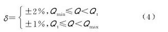
Where: δ is the relative error of measurement; Qmax is the maximum flow condition, m3/h; Qmin is the minimum flow condition, m3/h; Qt is the demarcation flow point, and its value is equal to 20% Qmax, m3/h.
Confirm whether the various installation positions affect the measurement performance of the test sample. The installation position can be divided into horizontal direction, vertical upward and downward. In the case of different installation positions, the change in indicating error of the prototype before and after the durability test must not exceed 1/3 of the required value of equation (4).
Take the DN80-G100 prototype as an example to illustrate the durability test. Firstly, three prototypes are installed at different positions in the same pipeline. The 0.8 MPa compressed gas in the pipeline is circulated with the maximum flow rate of the prototype, and every 1 000 h is used as the operating unit. The prototype is disassembled and the corresponding performance is performed on the standard gas flow device. The test results in 7 000 h operational test data (Figure 1).
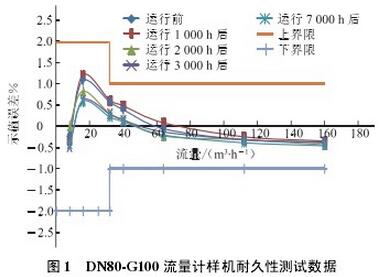
The results show that the test sample satisfies the durability test requirements, and the variation of the indicated error does not exceed 1/3 of the maximum allowable error; the running of the bearing is more stable after a long time running, and the nonlinear section tends to be more ideal after long-term operation. .
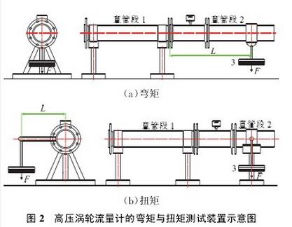
1.2.2 bending torque test
For high-pressure turbine flowmeters, the level of protection required by the flowmeter for bending and torsion moments should be specified [2]. This data can be obtained directly from the test (Fig. 2, in which the straight pipe section 1 is connected to the standard gas flow device, and in Fig. 2a the vertical force F is added to the predetermined arm L position of the straight pipe section 2 to form the bending moment M; Fig. 2b A force T in the vertical direction is added to a predetermined force arm L position on the side of the straight pipe section 2 to form a torque T, and the bending moment and the torque act on the flow meter inlet and outlet flanges). Since this test is mainly aimed at the verification of the flowmeter strength, in order to make the test results more convincing and improve its reliability, the low-voltage turbine flowmeter DN80-G100 of the aluminum alloy housing was used for this test. During the test, weights F of 1x, 2x, up to 4x (ie a torque of 3 040 N·m) were applied in accordance with Table 10 of EN 12261-2002. No abnormal changes were found in the flow meter housing. There is no significant change in the indication error obtained when the weight F is applied and after removing the weight, and the indication error before the weight F is applied. The actual variation is within 1/3 of the maximum allowable error.
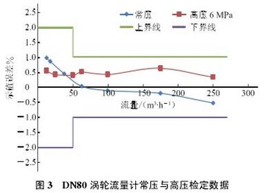
1.2.3 Comparison between normal pressure and high pressure test
In order to confirm whether the metering performance of the high-pressure turbine flowmeter in the high-pressure gas medium meets the industrial trade measurement requirements, multiple DN80-G160 prototypes were sent to the National Oil & Gas Large Flow Measurement Station Nanjing Substation for 6 MPa real-flow verification. The DN80 turbine flowmeter No. 131228041 was certified using a small flow standard device (Figure 3). The calculation formula of the meter coefficient K of the flow meter [10]: 
In the formula, (Ki)max, (Ki)min are the maximum value and the minimum value of Ki obtained by the flowmeter at each flow verification point in the qt~qmax flow range.
2 FC flow computer
The flow computer is a new generation of industrial micro-computer-based measuring instruments that can collect data at multiple flow measurement points, perform high-precision compensation calculations, store and display data, and use the network to achieve communication functions. Compared with the volume corrector, the data acquisition frequency is high, the operation speed is fast and accurate, and temperature pressure correction and metering can be performed on multiple flowmeters at the same time, widely used in petroleum, chemical industry, metallurgy, electric power, city gas and heating, etc. Industry's important trade measurement occasions and factory measurement management network.
The FC type flow computer can connect up to 4 flow meters and can be used with turbine flow meters, waist wheel flow meters, vortex flow meters, and orifice flow meters. When the flow input is a pulse signal, its volume flow is:
Qv=3 600 f/K ?????????????????(6)
Where: Qv is the unmodified volumetric flow, m3/h.
When the orifice flowmeter is connected, the volume flow is [11]: 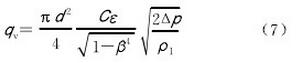
Where: qv is the volumetric flow rate under working conditions, m3/h; d is the opening diameter of the orifice plate under working conditions, mm; C is the outflow coefficient; for the orifice plate, it is calculated according to the standard; ? is the coefficient of expansion; ? is the section Flow equivalent diameter ratio; Δp is the pressure difference when the medium flows through the orifice, kPa; 11 is the density of the medium under working conditions, kg/m3.
In addition, the FC-type flow computer also has an energy metering function. It can directly receive the gas chromatograph's component analysis results through the configured RS485 communication interface, and can calculate the heat after the flow computer manually inputs the natural gas component data. Calculate the standard volume of gas to calculate natural gas energy [12]:
E=∑VnHs???????????????? (8)
In the formula: E is the energy of natural gas, kW · h; Vn is the volume of natural gas in the reference state, m3; Hs is the unit calorific value in natural gas reference state, MJ/m3.
The FC type flow computer has a variety of compression factor calculation models and contains a variety of communication interfaces. The RS485 interface can be used to communicate with the host computer or chromatograph, and the Modbus/TCP communication protocol can be used to communicate with the host computer through the RJ45 interface.
In order to meet the requirements of flow computer for the rapid processing of multi-channel data, at the same time, taking into account the flexibility of the flow computer hardware configuration, the FC type flow computer adopts a modular structural design scheme, and the data acquisition module adopts a pluggable board format. Each board card is equipped with a separate microprocessor, and the processor is responsible for receiving and processing electrical signals related to flow, temperature, and pressure input to the data acquisition module. At the same time, the data acquisition module can perform correspondingly according to different input signals. The configuration (Figure 4). 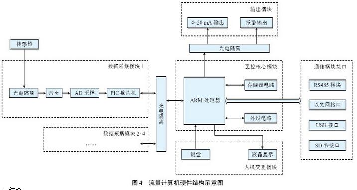
4 Conclusion
Through more than half a year of on-site industrial testing, the accuracy of high-pressure turbine gas flowmeters and supporting flow computers meets the design requirements. With high reliability, the indicators and technical performance fully meet the requirements of industrial trade measurement, breaking the long-term foreign high-pressure transmission. The technical monopoly in the field of pipelines has accumulated certain experimental data and experience, laying a solid foundation for the long-term operation of high-pressure long-distance transmission pipelines in the future. With the development of China's industrial metrology business and city gas, and the gradual implementation of energy metering, localized flow meters have a strong market competitiveness and a large market potential, and also provide technical support for natural gas metering management.
Guangzhou Quanxu Technology Co Ltd , https://www.skychema.com